GoodGraphics20.png, Glow Mapping Actually Works As Intended

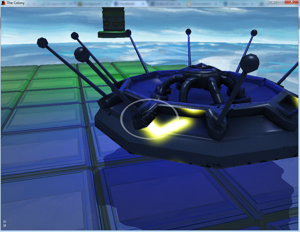
Like I mentioned in my previous post, in implementing my emissive mapping, I had a huge breakthrough that allowed me to fix my runtime glow mapping system to do what I had always intended.  While it provided a unique effect, the previous implementation had weird black borders that I couldn’t seem to get rid of and which prevented it from looking like the nice, blurred glow that I wanted.  The solution, it turned out, was very simple.

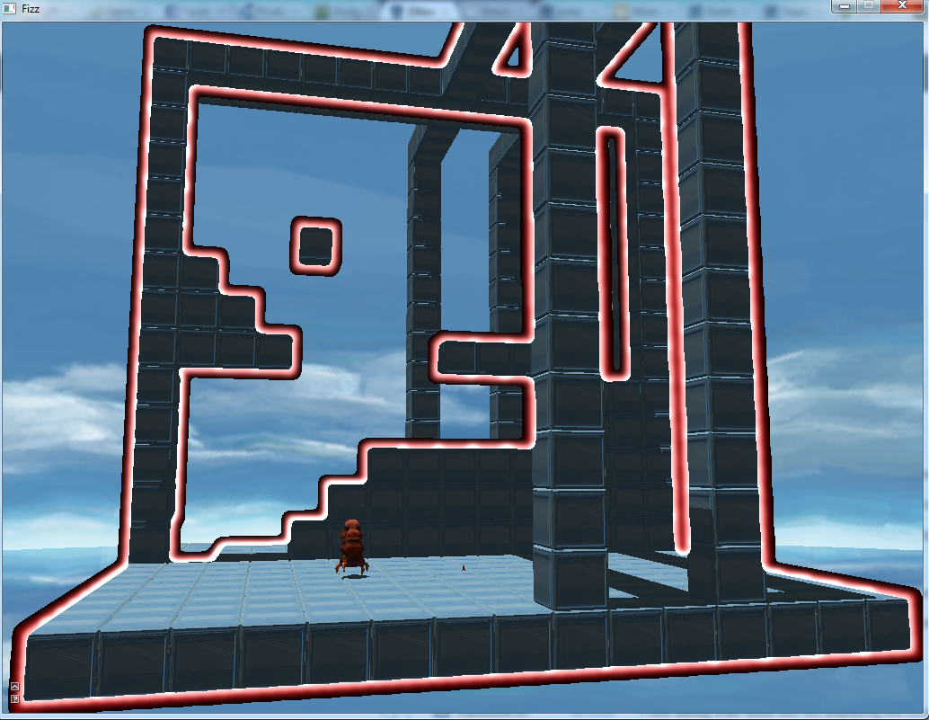
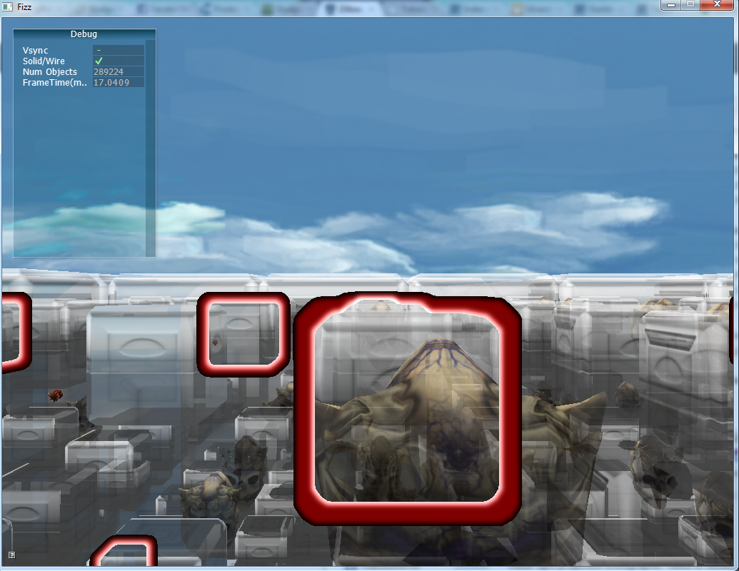
The fix was doing purely additive blending in my post processing.  Previously, I had figured that doing this would create an undesired effect were something to be a different color underneath.  Looking back, I have no idea why I thought that, it’s obviously wrong.  The original test I was performing was just to reject black pixels as a mask and layer on anything else over the final scene.  So, it should make perfect sense why there was a black band around the glow outlines; the blur created many pixels that were nearly black, but not quite, so they all passed the test and got layered in.  By switching to a pure additive system, the closer to black a pixel was, the less impact it had in the final composite scene.  And I finally had the effect I was after the whole time.  Like 5 months later.  I am smart.

This image was taken on 2/3/13.

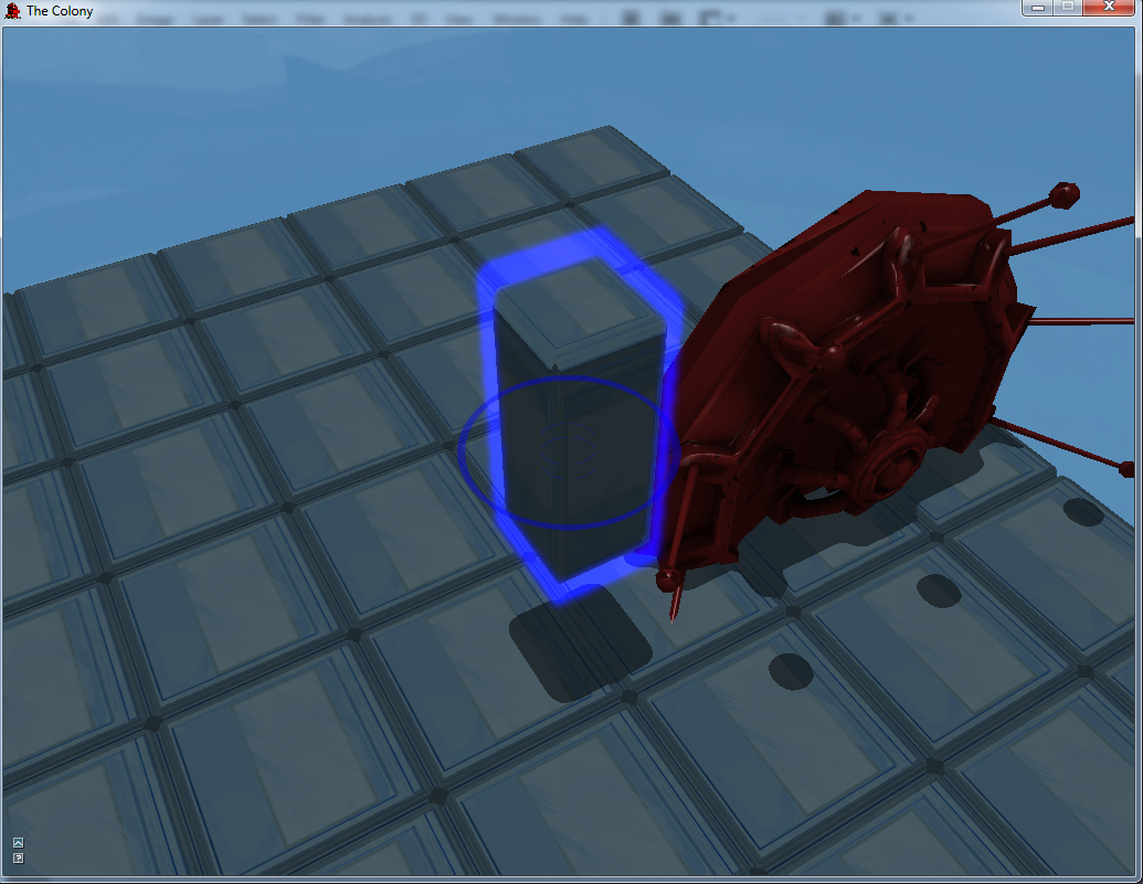
GoodGraphics20.png, glowing glow outlines.

GoodGraphics19.png, Emissive Mapping And A Huge Timeskip

Like I said in the previous post, for some reason there’s a huge timeskip in these progress images.  Also, we skip 18 for some reason.  I have no idea what happened there, but now it’s on purpose.  I’ll probably need to take some screen captures of some of the other features I implemented between this and the 17_X images and then screw up the chronological order completely.

So, this was the implementation of emissive mapping.  A lot of terms get thrown around to mean the same thing when we start talking about this, and also a lot of different, but similar, concepts start to get referred to with the same terminology.  So, it gets confusing.  For my purposes, emissive mapping refers to the process of taking an artist made texture and applying it along uv coordinates to meshes to denote sections of the model that are light sources and therefore glow.  It was a pretty simple feature to implement, but in doing so lead to a breakthrough in my glow mapping (runtime generated glows) that will end up being the basis of the next image post.

Also, you’ll notice some point lights here.  I probably won’t cover those in their own post because they were part of an extremely limited implementation that I’ve since discarded in favor of implementing a light pre-pass system.  But let’s not get ahead of ourselves here!

This image was taken on 2/3/13.

GoodGraphics19.png, emissive mapping and pointlights we won’t talk about.

GoodGraphics17_X.png, Artists Want Progress Shots, I Am Bad At Taking Them

These are actually the last progress shots I have for the semester.  While my memory on why is a little hazy, I’m going to claim that it was an intense semester for me and finishing all of my other classes and getting things implemented in the graphics engine was enough work without having to remember to take new progress shots.  Yeah, that’s the ticket.

So, there isn’t necessarily any big new features being documented in these image captures. My artists and producer wanted new progress shots so I took some that showed overall progress rather than any individual feature.  What I can claim here is that shadow mapping was cleaned up a lot to provide better, crisper shadowing.  Also, I had just tracked down a bug in my asset caching system; the system worked perfectly until it tried to cache mesh data between frames.  Something about what DirectX does while state changing between render frames caused bizarre vertex deformation when I tried to cache between frames.  While the bug had presented in multiple ways that weren’t obvious for months, I had finally tracked it down and solved it simply by forcing a recache at the start of each frame.  I was simultaneously pleased that I had solved it and angry that it had taken me so long to figure out the root issue.

Also, most of these images don’t do a great job of capturing the state of the graphics engine.  One makes it look like the scuttle casts no shadow and one is a goofy capture of what happens when you toggle wireframe mode with glow outlines active.  But, here they are anyway.

These images were taken on 10/25/12.

GoodGraphics17.png, a good progress shot of the graphics engine.

GoodGraphics17_2.png, wireframing glow outlines.

GoodGraphics17_3.png, this is a goofy picture of nonsense.

GoodGraphics17_4.png, good self shadowing on the scuttle.

Prototype Video

This is a quick video I put together after our Prototype milestone presentation.  There’s nothing major going on here graphically that wasn’t already touched on in previous posts, but it’s the first implementation of game mechanics and it looks much better than anything previous with updated assets from Ian.  It’s also the first good look at all of the graphics tech that I’d built being used together since the last milestone’s video.

This video was taken on 11/1/12.


GoodGraphics16.png, Finally Embracing Transparency

Despite offering the glow outline as a substitute for doing model transparency, the designers eventually wanted it anyway.  This was the first pass at it, and it was fairly successful.  I had to handle an intermediate accumulation step for drawing so that objects could be sorted between transparency and not, and then transparent objects could be distance sorted.  This first iteration only did a front face pass, so while the transparency effect was achieved, there was no volumetric depth to transparent models.  At the time, this wasn’t seen as an issue, and so transparency did not see improvement for a while after this.

This image was taken on 10/18/12.

GoodGraphics16.png, basic model transparency.